


 +86-19925192007
+86-19925192007
+86-19925192007


Time:2023-04-06 Views:1
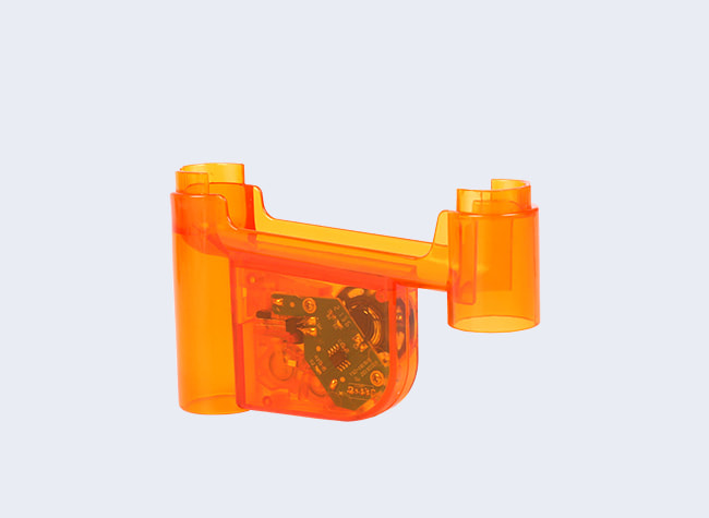
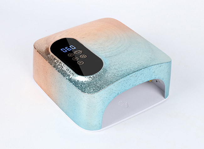
This utility model provides a multifunctional Nail Polish Dryer, which can effectively solve the above -mentioned background technology that the Nail Polish Dryer on the market is simple, single -function, can only be used for drying without other functions. The waiting time is long, which is boring for users. Although it can be entertaining through mobile phones, it is inconvenient to use mobile phones and charging with one hand.
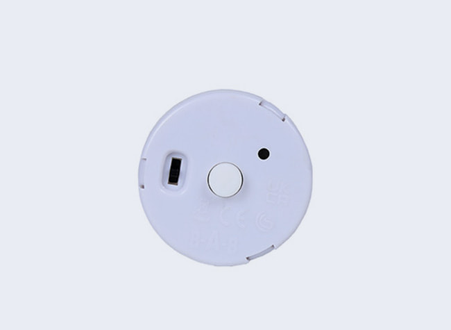
In order to achieve the above -mentioned goals, the use of the above -mentioned new model provides the following technical solutions: a multi -function Nail Polish Dryer, including dryer cases, winding racks, connecting grooves, charging holes, heating boards, LED lamp beads, fixed boards, circuit board boards , Control switch, rotation axis, handle, wire, USB connector, installation slot, outhole, slider, fixed convex block, card block, support plate, baffle, first fixed fixture, activity rod, and second fixed fixture. There is a winding frame on the left side of the dryer shell, which is opened with a connected groove on the top of the dryer shell, which is set with a charging hole on the left side of the groove. There is a fixed board above the heating board, which is installed with LED lamp beads installed in the middle of the fixed board, which is set up above the fixed board. The input end of the heating board is connected to the output end of the circuit board, the input terminal of the circuit board and the output terminal electrical connection of the control switch, the input terminal of the control switch and the output end electrical connection of the municipal power, and the output end electrical connection of the municipal power. The left side of the circuit board is set with a rotation shaft, which is set with a handle on the left side of the rotating shaft, which is wrapped around the outer side of the rotor. Electrical connection, a installation slot is opened in the middle of the axle, which is set with an informal hole in the left part of the installation slot. There is a slider at the top right of the rotary shaft. There are cards on the upper end. There is a support plate above the slider, and a baffle is set on the right side of the support plate. The second fixed fixture is set on the middle of the left side of the support plate. The rod, the first fixed fixture is set at the bottom left of the activity rod.
 +86-19925192007
Address: No. 2 Factory Workshop, Fukang Road, Pinghu Community, Pinghu Street, Longgang District, Shenzhen
Tel: +86-19925192007
E-mail: info@taishida.com


 Home >


